A comprehensive technical reference for architects, builders, contractors, remodelers, and accessibility specialists planning a Vuelift Mini home elevator installation
Introduction
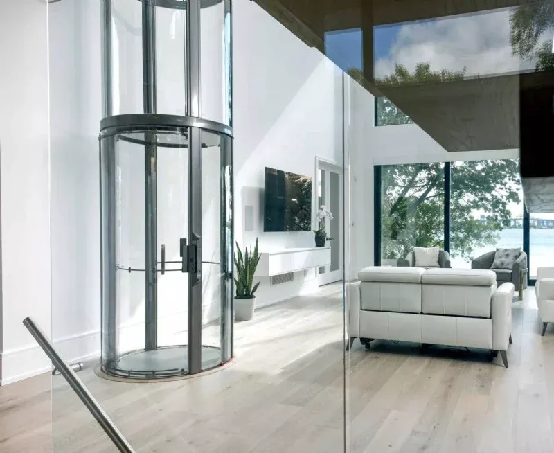
The Savaria Vuelift Mini is a compact, cylindrical residential elevator designed to blend modern aesthetics with practical vertical transportation in private homes. Unlike traditional boxed hoistways, the Vuelift Mini features a transparent circular shaft — available in clear acrylic or silica glass panels — that becomes an architectural feature rather than a hidden utility. Its small footprint (under 50 inches in diameter) makes it viable for both new construction and retrofit projects where space is limited.
This guide consolidates the critical planning data that architects, general contractors, structural engineers, and trade professionals need during the design and pre-construction phases. Every dimension, load figure, and electrical specification referenced here is drawn directly from Savaria's official Vuelift Mini Planning Guide (Part No. 001255, Rev. 24-m03-2023). However, this document is intended for initial planning only — always obtain site-specific installation (shop) drawings from Savaria or your authorized Savaria dealer before beginning construction.

1. Core Specifications at a Glance
Before diving into detailed planning sections, the table below provides the essential specifications that drive design decisions.
| Load Capacity | 500 lb (227 kg) |
|---|---|
| Maximum Travel | 50 ft (15.24 m); 55 ft (16.76 m) where variance is possible |
| Travel Speed | 30 ft/min (0.15 m/s) |
| Noise Level | 58–60 dB (typical installation) |
| Maximum Stops | 6 |
| Overall Footprint (Pit Ring Diameter) | 49.75 in (1,264 mm) |
| Hoistway Ring Diameter | 43.75 in (1,111 mm) |
| Acrylic/Glass Cab Diameter | 42.8 in (1,082 mm) |
| Cab Interior Height | 77.75 in (1,975 mm) |
| Cab Floor Area | 8.25 sq ft (0.76 sq m) |
| Cab Weight — Acrylic | 550 lb (250 kg) |
| Cab Weight — Glass | 1,000 lb (455 kg) |
| Minimum Overhead Clearance | 96 in (2,438 mm) |
| Minimum Distance Between 2 Landings | 93 in (2,362 mm) |
| Pit Depth (Minimum) | 3 in (76 mm); 4 in (102 mm) with buffer springs |
| Pit Depth (Maximum) | 12 in (305 mm) |
| Power Supply — Motor | 230V, single-phase, 30A fused disconnect with 20A fuse/breaker |
| Power Supply — Cab Lighting | 115V, single-phase, 15A |
| Drive System | Winding drum, 2.2 HP (1.63 kW) @ 60 Hz with integrated brake |
| Motor Control | Preprogrammed variable frequency drive |
| Operating Temperature Range | 14°F to 104°F (−10°C to +40°C) |
Daily Cycle Limits
Understanding cycle limits is important for projects where the elevator may see heavier-than-typical residential use.
| Normal | 40 | 20 |
|---|---|---|
| Heavy | 80 | 20 |
| Excessive | 150 | Consult Savaria |
Note: Each landing should be in a climate-controlled environment for optimal running conditions.
2. Model Configurations: Acrylic vs. Glass
The Vuelift Mini is available in two cab material options, each with distinct weight implications for structural planning.
Type 1 vs. Type 2
The Vuelift Mini offers two configuration types — Type 1 and Type 2 — which differ primarily in the orientation of the cab door and the position of the drive components within the hoistway. Both types share the same footprint and structural requirements. Your choice between Type 1 and Type 2 is typically driven by the desired door swing direction relative to the surrounding floor plan.
Material Comparison
| Cab wall material | Full clear acrylic | Silica glass |
|---|---|---|
| Cab weight | 550 lb (250 kg) | 1,000 lb (455 kg) |
| Visual effect | Lightweight, modern | Premium, high-end |
| Structural load impact | Lower floor load requirements | Higher floor load requirements — plan accordingly |
| Controller box width | 6.793 in (172.53 mm) | 7.793 in (197.93 mm) |
Standard and Optional Colors
The standard frame color is Texture Black (PX622N365). Optional colors include Texture White (PX521W859), Texture Silver (PX521S343), and custom powder-coat finishes. Landing door handles and top header rings can also be painted to match.
Available Options
The Vuelift Mini supports a range of optional features including Savaria Link remote monitoring, a pitless option with ramp, Sabbath service, flood switch, buffer springs for habitable space below, buck-boost transformer, balcony attachment or thru-floor configuration, cab shipped disassembled, and the ability to service up to 6 stops.
3. Structural Requirements and Load Calculations
This is the section that your structural engineer will reference most heavily. The Vuelift Mini transfers its dead load and impact load to the lowest level through four support columns that run from top to bottom of the elevator. These loads are carried through rail base plates and rings.
How Loads Are Distributed
Primary loads are carried by four support columns running the full height of the installation. The total load is supported on 4 in × 4 in plates at the bottom of each column. All mid-floors (including the bottom floor) may be subjected to a maximum lateral load of 200 lb. The elevator is designed for buildings that maintain consistent floor-to-floor height; if floor-to-floor height changes after installation, the elevator must be taken out of service pending inspection.
Load Calculation Formulas
These formulas calculate the pit floor load. Floor load figures include the elevator structure weight when loaded with full test capacity, but they do not include your safety factor. Your building engineer must add an appropriate factor of safety — many jurisdictions require at least a factor of 4.
Glass Model — Pit Floor Load:
| Dead Load (lbs) | (ft of hoistway × 65) + (number of floors × 249) + 1,885 |
|---|---|
| Dead Load (kg) | (m of hoistway × 97) + (number of floors × 113) + 855 |
Acrylic Model — Pit Floor Load:
| Dead Load (lbs) | (ft of hoistway × 65) + (number of floors × 149) + 1,485 |
|---|---|
| Dead Load (kg) | (m of hoistway × 97) + (number of floors × 68) + 674 |
Example Calculation (Glass, 2-Stop, 10 ft Travel)
Using the glass formula: (10 × 65) + (2 × 249) + 1,885 = 650 + 498 + 1,885 = 3,033 lbs pit floor load before safety factor. With a safety factor of 4, engineer the floor for approximately 12,132 lbs.
Critical Structural Notes
- Walls of brick, terra-cotta, hollow blocks, and similar materials shall not be used for attachment of column (guide rail) brackets unless adequately reinforced.
- Where necessary, building construction shall be reinforced to provide adequate support for the guide rail columns.
- Floor load figures shown in the planning guide are actual loads — your building engineer must add the appropriate safety factor per local codes.
- The elevator is designed for applications in buildings that maintain consistent floor-to-floor heights as the building ages.
4. Floor Opening and Shaft Planning
The circular hoistway is one of the defining features of the Vuelift Mini, but it demands precise floor cutouts and careful attention to clearances at every landing.
Key Dimensions
| Pit ring diameter (overall footprint) | 49.75 in (1,264 mm) |
|---|---|
| Hoistway ring diameter | 43.75 in (1,111 mm) |
| Thru-floor cutout diameter | 43.75 in (1,111 mm) |
| Cab acrylic/glass diameter | 42.8 in (1,082 mm) |
| Clear cab interior (usable) | 39.4 in (1,000 mm) |
Thru-Floor vs. Balcony Configuration
The Vuelift Mini can be installed in two landing configurations:
Thru-Floor Configuration: The elevator passes through a circular cutout in the floor structure. This is the most common approach in new construction where framing can be planned around the elevator from the start. The cutout must match the hoistway ring diameter precisely — any misalignment will create installation problems.
Balcony Configuration: At upper landings, the elevator can extend alongside a balcony or mezzanine edge rather than passing through the floor. This approach avoids cutting the floor structure and can be useful in retrofit projects. Handrails at balcony levels are required per local codes and must be provided and installed by the contractor — Savaria and the local installer are not responsible for handrail installation or materials.
Planning the Circular Cutout
When framing for the thru-floor cutout, keep in mind that the 43.75 in hoistway ring needs to sit precisely within the floor opening. The pit ring at the base level is larger at 49.75 in diameter. Ensure that surrounding floor joists or structural members are adequately headed off to maintain structural integrity around the circular penetration. A structural engineer should review the framing plan for each floor penetration.
5. Pit Requirements
The Vuelift Mini requires a shallow pit at the lowest landing — one of its most builder-friendly features compared to traditional residential elevators that may require pits of 24 inches or more.
Pit Depth Specifications
| Standard installation | 3 in (76 mm) |
|---|---|
| With buffer springs (required if habitable space below) | 4 in (102 mm) |
| Maximum pit depth | 12 in (305 mm) |
For pit depths greater than 12 inches, contact Mobility123 to ensure proper equipment will be provided.
Pit Construction Requirements
The pit floor must be a smooth, level surface capable of bearing the calculated load. It is recommended that the pit floor and walls be finished prior to installation because they remain visible after the elevator is installed — the transparent shaft means the pit area is part of the visual presentation.
If a pitless installation is preferred, Savaria offers a pitless option with a ramp. This eliminates the need for any floor excavation and can simplify retrofit projects significantly.
Wire Routing From Pit
Conduit routing from the pit to the machine room/controller is a critical coordination item. Key requirements include:
- Minimum 1-1/4 in (31.75 mm) steel rigid conduit
- Must run at least 2 conduits
- Encoder wire must NEVER be in the same conduit as the motor wire
- If pulling 3 wires (2 round 30 conductor and 1 motor wire), use at least 2 in (50.8 mm) or pipe with 90-degree bends and 70 ft (21,336 mm) of pipe
- If pulling 2 wires (1 round 30 conductor and 1 motor wire), use at least 1.5 in (38.1 mm) conduit with 90-degree bends
- If running through a wall with no conduits, you must have a minimum of 24 in (609.6 mm) between motor wire and encoder wire
- Bigger diameter conduit is recommended for deeper pits
- Adjust pit depth according to conduit minimum requirements
6. Overhead Clearance and Ceiling Height
Adequate overhead clearance is non-negotiable for code compliance and safe operation.
Minimum Overhead Requirements
The minimum overhead distance from the upper floor level to the underside of the finished ceiling or any obstruction is 96 inches (2,438 mm). This measurement is taken from the top landing floor level straight up to the lowest point of the ceiling, beam, duct, or any other obstruction above the hoistway.
What "Overhead" Includes
When measuring overhead clearance, account for finished ceiling material, HVAC ducts, plumbing runs, structural beams, lighting fixtures, sprinkler heads, and any other element that projects below the structural ceiling plane. The elevator's head assembly and machine room components will occupy the space at the top of the hoistway.
Machine Room / Controller Placement
The controller is located at the top of the hoistway. The machine room area requires:
- 12 in (305 mm) clearance from the hoistway centerline for the machine room layout
- Space for the controller box — dimensions vary by model:
- Acrylic units: 24.25 in W × 20.385 in H × 6.793 in D (615.95 × 517.78 × 172.53 mm)
- Glass units: 24.25 in W × 20.385 in H × 7.793 in D (615.95 × 517.78 × 197.93 mm)
- The remote controller cannot be more than 100 ft (30.48 m) from the top of the unit
Suggested conduit from the machine room runs through the ceiling, with a minimum 2 in (50.8 mm) diameter for runs greater than 480 in (12,192 mm). Dashed areas on Savaria's drawings indicate acceptable locations for conduit at the top of the hoistway for the remote controller and power for the head assembly.
7. Electrical Requirements
Electrical coordination is one of the most common sources of delays on elevator projects. Having the correct power in place before the installation crew arrives is essential.
Required Electrical Connections
| Motor and equipment | 230V | Single | 30 Amps | 20 Amps |
|---|---|---|---|---|
| Cab lights | 115V | Single | 15 Amps | 15 Amps |
| Pit light (if required) | 115V | Single | 15 Amps | 15 Amps |
Additional Electrical Requirements
- Main Disconnect: One 230V single-phase, 30 Amp fused disconnect box with 20 Amp fuse/breaker. If voltage is not 230V minimum, a buck-boost transformer is required (available as an option from Savaria).
- Lighting Disconnect: One 120V, 15 Amp fused disconnect or circuit breaker for cab lighting. A second 110V, 15A disconnect is also required, mounted near the 230V disconnect.
- Telephone Line: One telephone line jack in close proximity to the controller. This can typically be the common house line — check with your local installer or building contractor for local code requirements.
- GFCI Outlet: One 15A GFCI outlet shall be installed near the pit or base ring.
- Savaria Link (if applicable): If using Savaria Link remote monitoring with antenna, ensure wireless internet capability near the controller. If using Savaria Link with Ethernet, ensure an Ethernet connection with internet capability near the controller.
Critical Electrical Notes
- Savaria does not provide power cable to the main disconnect — this must be run by the project electrician.
- Lockable fused disconnects must be installed in compliance with electrical code and must be provided prior to installation.
- The disconnect switch must be mounted in a location within line of sight of the elevator or controller.
- 230V source must be run from the disconnect switch to a junction box in a discrete location at the top of the elevator hoistway.
- Permanent power must be supplied before installation can begin — the elevator cannot be installed on temporary construction power.
8. Elevator Location Best Practices
Choosing where to place the Vuelift Mini within the floor plan has implications for structural framing, traffic flow, visual impact, and long-term livability.
Ideal Placement Considerations
Structural simplicity: Locate the elevator where the circular floor cutouts can be framed without disrupting primary load-bearing members. A location near the center of a joist bay (rather than directly over a beam) often simplifies the header framing required around the circular opening.
Traffic flow: Position the elevator where it connects naturally to the home's circulation pattern. Near a main staircase is a common choice, it creates a logical vertical transportation zone and simplifies wayfinding for visitors and service providers.
Visual impact: The transparent shaft is a design feature. Consider placing the elevator where its glass or acrylic panels can be seen and appreciated; a two-story foyer, an open living area, or adjacent to a feature wall. The pit area is visible through the transparent panels, so a finished pit is recommended.
Noise considerations: At 58–60 dB during operation, the Vuelift Mini is comparable to a normal conversation. However, placing it away from primary bedrooms and quiet zones is still advisable, particularly in homes where the elevator may be used during nighttime hours.
Service access: Ensure the machine room area at the top of the hoistway is accessible for maintenance. The controller must have a line-of-sight disconnect, and a service technician needs reasonable access to the top of the shaft.
Corner Installation
Savaria provides specific drawings for corner installations where the elevator is positioned at the intersection of two walls. This configuration can be space-efficient and provides structural backing on two sides, but requires careful attention to the clearances between the circular hoistway and the adjacent wall surfaces.
9. Glass and Acrylic Shaft Integration
The transparent hoistway is what sets the Vuelift Mini apart visually, but it also introduces coordination requirements that traditional enclosed hoistways do not.
Acrylic Panels
Acrylic panels offer a lightweight option (cab weight of 550 lb vs. 1,000 lb for glass) and provide excellent optical clarity. They are more resistant to impact than glass but may show surface scratching over time if not maintained. The lighter weight reduces structural load requirements.
Glass (Silica) Panels
Glass panels deliver a premium aesthetic with superior scratch resistance and long-term clarity. However, the significantly higher cab weight (1,000 lb) means your structural engineer needs to account for nearly double the cab weight in load calculations compared to acrylic.
Design Coordination for Transparent Shafts
Because occupants and visitors can see into and through the hoistway, every element within the shaft must be finished to a presentable standard. This includes the pit floor and walls (which should be finished before installation), any visible structural framing around floor cutouts, and the landing areas at each stop. Consider lighting adjacent to the shaft — it will affect how the elevator looks from different angles throughout the day.
The transparent panels also mean that anything stored near the elevator's path of travel will be visible. Coordinate with the homeowner's interior designer to ensure the shaft becomes a visual asset rather than an afterthought.
10. Safety Code Compliance
ASME A17.1 / CSA B44 Compliance
The Vuelift Mini meets the requirements of ASME A17.1/CSA B44 Safety Code for Elevators and Escalators across multiple code editions, from Part 5 of the 1996 edition through Section 5.3 of the 2019 edition. Contact your local authority having jurisdiction (AHJ) to confirm which code edition applies to your project.
The 3/4 & 4 Rule (Code 2016 and After)
The ASME A17.1-2016/CSA B44-16 code mandates specific hoistway door clearances:
- Clearance between the hoistway door and the hoistway edge of the landing sill shall not exceed 0.75 in (19 mm).
- Distance between the hoistway face of the landing door and the car door shall not exceed 4 in (102 mm).
- The Vuelift Mini is designed with a maximum 1.25 in (32 mm) running clearance.
Built-In Safety Features
The Vuelift Mini includes the following standard safety features: pit run/stop switch and car top run/stop switch, emergency stop switch, safety brakes, overspeed governor, manual lowering capability, and emergency battery back-up for cab lighting and lowering.
Habitable Space Below
If there is habitable space below the elevator, buffer springs are required. This increases the minimum pit depth from 3 in to 4 in (76 mm to 102 mm). Buffer springs are available as an option from Savaria.
11. Trade Coordination Checklist
A successful Vuelift Mini installation requires coordination across multiple trades. Miscommunication between trades is the most common source of costly change orders on elevator projects.
General Contractor / Builder
- Verify all clearance dimensions prior to delivery
- Ensure floors are in finished state prior to installation
- Provide all masonry, carpentry, and drywall work as required
- Coordinate floor cutout locations with structural engineer
- Schedule trades in proper sequence (structural → electrical → elevator installation)
Structural Engineer
- Calculate floor loads using Savaria's formulas plus appropriate safety factor
- Verify building will safely support all loads imposed by the elevator
- Design header framing around circular floor penetrations
- Assess lateral load capacity at all mid-floor levels (200 lb maximum lateral load)
- Confirm consistent floor-to-floor heights
Electrician
- Install 230V, single-phase, 30A dedicated power with lockable fused disconnect (cartridge type)
- Install two 110V, 15A disconnects with lockable fused disconnect
- Run 230V from disconnect to junction box at top of hoistway
- Disconnect switch must be within line of sight of elevator or controller
- Install 15A GFCI outlet near pit or base ring
- Install telephone line jack near controller location
- Coordinate conduit routing from pit to machine room area
- All electrical work must be complete with permanent power before installation begins
Framing Carpenter
- Frame circular floor openings to precise dimensions (43.75 in hoistway ring diameter)
- Reinforce opening headers per structural engineer's specifications
- Ensure smooth, level surfaces at all landing levels
- Construct pit (if applicable) with smooth, level floor surface
Finish Trades
- Complete all finished flooring at every landing level before elevator installation
- Finish pit floor and walls before installation (visible through transparent panels)
- Install handrails at all balcony levels per local codes after elevator installation
- Coordinate interior finishes adjacent to transparent shaft for visual presentation
12. Common Planning Mistakes to Avoid
Based on field experience, the following issues cause the most delays and cost overruns on Vuelift Mini projects.
Insufficient overhead clearance. The 96-inch minimum is measured to the underside of the finished ceiling or any obstruction — not the structural deck above. HVAC ducts, plumbing, and sprinkler lines frequently encroach on this clearance. Measure to the lowest point of everything above the hoistway.
Temporary power instead of permanent power. The elevator cannot be installed on temporary construction power. Permanent 230V power must be in place before the installation crew arrives. This catches many builders who plan to run permanent power later in the construction sequence.
Unfinished pit surfaces. Because the shaft is transparent, the pit floor and walls are visible after installation. If these surfaces are left as raw concrete or unfinished, they will be visible through the acrylic or glass panels indefinitely. Finish the pit before the elevator goes in.
Ignoring the weight difference between acrylic and glass. The glass cab weighs nearly twice as much as the acrylic cab (1,000 lb vs. 550 lb). This difference significantly affects the load calculation. Specifying acrylic and then switching to glass mid-project can require structural reinforcement.
Forgetting conduit routing. Wire routing from the pit to the controller at the top of the hoistway requires pre-planned conduit runs. The encoder wire and motor wire must be in separate conduits. Retrofitting conduit after walls and ceilings are closed is expensive.
Inadequate floor-to-floor distance. The minimum distance between two landings is 93 inches (2,362 mm). Verify this before committing to floor-to-floor heights — some renovation projects with non-standard ceiling heights may fall short.
Not accounting for the safety factor in floor loads. Savaria's load figures are actual loads without safety factors. Many jurisdictions require a safety factor of 4, which means the engineered floor capacity needs to be four times the calculated load. Missing this can trigger a failed structural inspection.
Controller distance exceeding 100 ft. The remote controller cable cannot exceed 100 ft (30.48 m) from the top of the unit. In large homes or installations where the controller is in a remote mechanical room, verify this distance during the planning phase.
13. Pre-Construction Checklist
Use this checklist to verify that all planning requirements are addressed before breaking ground or beginning demolition for a Vuelift Mini installation.
Design Phase
- [ ] Confirm client's intended use and daily cycle requirements
- [ ] Determine applicable local code edition (ASME A17.1 year)
- [ ] Select cab material (acrylic or glass) — this affects all load calculations
- [ ] Select configuration (Type 1 or Type 2) based on desired door orientation
- [ ] Determine number of stops and total travel distance
- [ ] Verify minimum 93 in floor-to-floor distance at all landings
- [ ] Verify minimum 96 in overhead clearance at top landing
- [ ] Determine pit configuration (standard pit, deep pit, or pitless with ramp)
- [ ] If habitable space below elevator, specify buffer springs
- [ ] Identify elevator location on floor plan with all required clearances
- [ ] Contact Mobility123 for site-specific shop drawings
Structural Engineering
- [ ] Calculate pit floor load using Savaria's formula for selected cab material
- [ ] Apply jurisdictional safety factor (typically 4x) to calculated loads
- [ ] Design header framing for circular floor openings at each landing
- [ ] Verify lateral load capacity at mid-floor levels (200 lb maximum)
- [ ] Confirm consistent floor-to-floor heights throughout the structure
- [ ] Ensure wall materials at column bracket attachment points are adequate (no unbraced masonry)
Electrical Planning
- [ ] Plan 230V, 30A dedicated circuit to top of hoistway
- [ ] Plan two 110V, 15A circuits (cab lighting, pit light if required)
- [ ] Identify disconnect switch location — must be within line of sight of elevator or controller
- [ ] Plan 15A GFCI outlet location near pit or base ring
- [ ] Plan telephone line to controller location
- [ ] Plan conduit routing from pit to machine room (minimum 2 conduits, encoder and motor wire separated)
- [ ] If voltage below 230V, specify buck-boost transformer
- [ ] If Savaria Link is desired, plan internet connectivity near controller
Pre-Installation Site Conditions
- [ ] All finished floors installed at every landing level
- [ ] Pit constructed with smooth, level surface (finished if visible)
- [ ] Floor cutouts complete and dimensionally verified
- [ ] Permanent 230V and 110V power installed and energized
- [ ] All disconnects mounted and accessible
- [ ] Telephone jack installed near controller location
- [ ] GFCI outlet installed near pit or base ring
- [ ] All clearance dimensions field-verified against shop drawings
- [ ] Handrail locations marked for post-installation work at balcony levels
14. Key Reference Dimensions — Quick-Reference Table
This table consolidates the most frequently referenced dimensions for framing and rough-in work.
| Pit ring diameter (base level footprint) | 49.75 in | 1,264 mm |
|---|---|---|
| Hoistway ring diameter | 43.75 in | 1,111 mm |
| Cab acrylic/glass diameter | 42.8 in | 1,082 mm |
| Clear cab interior diameter | 39.4 in | 1,000 mm |
| Cab interior height | 77.75 in | 1,975 mm |
| Minimum overhead clearance | 96 in | 2,438 mm |
| Minimum distance between 2 landings | 93 in | 2,362 mm |
| Minimum pit depth (standard) | 3 in | 76 mm |
| Minimum pit depth (buffer springs) | 4 in | 102 mm |
| Maximum pit depth | 12 in | 305 mm |
| Floor in cab (by others) — maximum thickness | 0.5 in | 12.7 mm |
| Controller box — width | 24.25 in | 615.95 mm |
| Controller box — height | 20.385 in | 517.78 mm |
| Controller box — depth (acrylic) | 6.793 in | 172.53 mm |
| Controller box — depth (glass) | 7.793 in | 197.93 mm |
| Maximum controller cable distance | 100 ft | 30.48 m |
| Machine room clearance from hoistway centerline | 12 in | 305 mm |
| Maximum hoistway door-to-sill clearance (2016+ code) | 0.75 in | 19 mm |
| Maximum landing door-to-car door distance (2016+ code) | 4 in | 102 mm |
| Running clearance | 1.25 in | 32 mm |
15. Applicable Codes and Standards
The Vuelift Mini has been designed and manufactured to meet the requirements of the following code editions. Confirm with your local authority having jurisdiction (AHJ) which edition applies to your project.
- ASME A17.1 1996, Part 5
- ASME A17.1/CSA B44 2000, Section 5.3
- ASME A17.1/CSA B44 2004, Section 5.3
- ASME A17.1 2004, Addendum 2005, Section 5.3
- ASME A17.1/CSA B44 2007, Section 5.3
- ASME A17.1/CSA B44, Addendum 2008, Section 5.3
- ASME A17.1/CSA B44 2010, Section 5.3
- ASME A17.1/CSA B44 2013, Section 5.3
- ASME A17.1/CSA B44 2016, Section 5.3
- ASME A17.1/CSA B44 2019, Section 5.3
16. Planning Workflow Summary
For architects and builders who want a streamlined process, here is the recommended planning sequence:
- Define the project scope — number of stops, total travel distance, cab material (acrylic vs. glass), configuration type (1 or 2), and any optional features.
- Engage a structural engineer early — the circular floor penetrations and concentrated column loads require engineering review before framing begins.
- Contact Mobility123 — obtain site-specific shop drawings. The planning guide dimensions are nominal; your project's actual dimensions may differ.
- Coordinate electrical rough-in — permanent 230V and 110V power, disconnects, telephone, GFCI outlet, and conduit routing should all be planned before walls are closed.
- Verify all pre-installation conditions — use the checklist in Section 13 to confirm that finished floors, power, cutouts, and pit are complete and dimensionally accurate.
- Schedule the installation — the Mobility123 installation team or authorized installer will complete the elevator installation once all site conditions are met.
- Complete post-installation items — handrails at balcony levels, final inspections, and any touch-up work around the shaft.
Important Disclaimer
This guide is based on the Savaria Vuelift Mini Planning Guide, Part No. 001255, Rev. 24-m03-2023. Dimensions and specifications are subject to change without notice due to product enhancements and evolving codes. This document is intended for initial planning purposes only. Before beginning construction, obtain site-specific installation (shop) drawings from Mobility123 or your authorized Savaria dealer. Visit savaria.com for the most current drawings and dimensions.
This guide was prepared by Mobility123 as a technical resource for construction professionals planning Vuelift Mini residential elevator installations. For project-specific guidance, free site evaluations, or to request a quote, contact Mobility123 at mobility123.com or call for a consultation.