What Is ASME A17.1 Section 7:
Who Needs to Know It?
ASME A17.1 (also published jointly as CSA B44) is the Safety Code for Elevators and Escalators. It is the primary code governing the design, construction, installation, operation, inspection, testing, maintenance, alteration, and repair of elevators, escalators, dumbwaiters, moving walks, and material lifts across the United States and Canada. Part 7 of this code applies specifically to dumbwaiters and material lifts, covering both electric and hydraulic drive configurations.
If you are a builder, architect, structural engineer, mechanical contractor, or code official involved in a project that includes a material lift, Part 7 is your governing reference. It determines the construction standards for the hoistway, the safety devices required on the car, the electrical and control system specifications, and the long-term inspection and maintenance obligations that follow the equipment throughout its service life.
Part 7 is organized into several sections. Section 7.1 covers general requirements for dumbwaiters. Sections 7.2 and 7.3 address electric and hydraulic dumbwaiters. For material lifts without automatic transfer devices, Section 7.4 establishes the general requirements (classification, hoistway, pit, clearances, door locking), Section 7.5 covers electric material lifts, and Section 7.6 covers hydraulic material lifts. Understanding which sections apply to your project depends on the drive type and classification of the lift. For a deeper look at how A17.1 relates to other accessibility codes, see this comparison of ASME A18.1 and ASME A17.1.
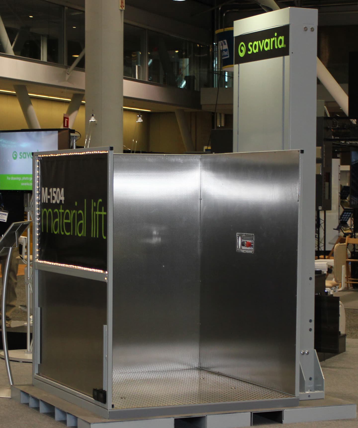
Throughout this guide, the Savaria M-1504 hydraulic material lift is referenced as a real-world example of how these code requirements translate into actual equipment design. The M-1504 is designed to comply with ASME A17.1 Sections 7.4, 7.5, and 7.6 as a Type B material lift, making it a useful reference point for understanding how code provisions manifest in practice.
Type A vs. Type B Material Lifts:
Classification and Key Differences
Section 7.4.2 of ASME A17.1 establishes two material lift classifications that affect nearly every downstream requirement, from enclosure height to control design. Choosing the correct classification is one of the first decisions in any material lift project, and getting it wrong can result in failed inspections, code violations, or costly redesigns.
A Type A material lift is designed to carry materials only. No person is permitted to ride the lift at any time. All operating controls are located at the landings (not inside the car), and the lift operates under continuous-pressure control from those landing stations.
A Type B material lift is designed to carry materials and one designated operator who rides with the load. The operator uses controls mounted inside the car (a car operating panel, or COP), and the lift also has landing call stations. Because a person rides the lift, Type B carries significantly more stringent requirements for enclosure height, safety devices, emergency controls, and speed limitations.
Table 1: Type A vs. Type B Material Lift Comparison
| Requirement | Type A | Type B |
|---|---|---|
| Rider permitted | No | Yes (one designated operator) |
| Operating controls | Landing stations only | Car operating panel (COP) + landing stations |
| Maximum speed | No specific limit in 7.4 | 0.15 m/s (30 ft/min) per Table 7.4.3 |
| Maximum travel | No specific limit in 7.4 | 7.6 m (25 ft) per Table 7.4.3 |
| Enclosure side height | Per Section 2.14 | 2,030 mm (80 in.) per Table 7.4.3 |
| Car height | Per Section 2.14 | 2,030 mm (80 in.) per Table 7.4.3 |
| Gate height | Per Section 2.14 | 2,030 mm (80 in.) per Table 7.4.3 |
| Operation type | Continuous pressure (CPLA) | Continuous pressure (CPPB) |
| Emergency stop in car | Not required | Required (Section 7.5.12.2.6) |
| Hoistway door close contacts | Not required | Required within 75 mm of landing (7.5.12.2.18) |
The Savaria M-1504, for example, can be installed as either a Type A or Type B material lift depending on the project requirements. In its standard Type B configuration, it provides an 80-inch cab wall height, a rated speed of 18 ft/min (well under the 30 ft/min maximum), a maximum travel of 23 ft, and a car operating panel with emergency stop, door open button, and landing call buttons. These specifications directly reflect the Type B requirements. When configured as Type A, the lift operates with landing-mounted controls only and does not permit a rider, which reduces some of the enclosure and control requirements. The classification decision should be made early in the design phase, as it affects hoistway construction, control wiring, and safety device requirements throughout the project.
Hoistway Construction Requirements
(Section 7.4.3)
Section 7.4.3 establishes that hoistway construction for material lifts shall conform to the general requirements of Sections 2.1 through 2.10, with several modifications specific to material lifts as listed in Table 7.4.3. A key distinction for material lifts is that non-fire-resistive construction is permitted where building codes allow it. This means that in many installations, the hoistway does not need to be built with fire-rated materials, which can simplify construction and reduce costs.
For Type B material lifts, the enclosure sides must extend to a minimum height of 80 in., and openwork construction (such as wire mesh or expanded metal) is permitted. The gate and car enclosure must also reach 80 in. These dimensions ensure that the riding operator is adequately protected during travel.
For hydraulic material lifts, Section 7.6.1 adds that hoistways, hoistway enclosures, and related construction shall conform to Sections 3.1 through 3.13 and 3.29, except as modified by Sections 7.4.3 through 7.4.16. This brings in the hydraulic-specific hoistway requirements from Part 3. For guidance on enclosure options and configurations, including fire-rated and non-fire-rated designs, builders should consult both the applicable building code and the equipment manufacturer’s planning documentation.
The M-1504 uses a modular tower assembly with an 8-foot base guide rail section. Tower extensions are added to reach the required travel height. The tower is anchored to the hoistway wall using lag bolts (for wood/drywall) or anchor wedge bolts (for concrete), with a required wall pull-out strength of 650 lb at each anchor point. The hoistway must be plumb, square, and level before installation begins, with rough openings, lintels, and grouting completed per the manufacturer’s site verification checklist. For NJ permitting guidance, visit our services page, with rough openings, lintels, and grouting completed per the manufacturer’s site verification checklist.
Pit Requirements & Structural Considerations
(Section 7.4.4)
Section 7.4.4 requires that pits for material lifts conform to the general pit requirements in Section 2.2, with modifications specific to the material lift application. The pit provides space for the buffer or bumper at the bottom of travel and ensures adequate clearance beneath the car platform when the lift is at its lowest position.
Pit depth varies based on the installation configuration and the applicable code edition. For the Savaria M-1504, the standard pit depth is 3 inches for general installations. When the lift is installed to ASME A17.1 standards, a 6-inch pit depth is required. If there is habitable space underneath the lift, the pit depth increases to 8 inches to provide adequate safety clearance. The pit floor and surrounding pad must be flat and level before the lift tower is positioned.
Structural considerations extend beyond the pit itself. The floor beneath the lift must support a concentrated load of 3,400 lb (the combined weight of the tower, car, and rated load). These structural requirements should be verified by a structural engineer during the design phase, not discovered during installation. For projects that involve navigating the permitting process, builders may find it helpful to review general guidance on permit requirements for lifts and elevators on permit requirements for lifts and elevators.
Car Enclosure & Platform Requirements
(Sections 7.5.1 through 7.5.3)
Section 7.5.1 requires that car enclosures conform to Section 2.14, which covers the general requirements for car enclosures, including wall construction, openings, and ventilation. For Type B material lifts, the critical modification from Table 7.4.3 is the 80 in. minimum height for enclosure sides, providing full-height protection for the riding operator.
Car frames and platforms (Section 7.5.2) must be designed and constructed to safely support the rated load plus the weight of the car structure itself. Section 7.5.3 addresses capacity and loading, requiring that the rated load conform to Section 2.16. The minimum rated load is calculated based on the greater of the actual maximum load to be handled or 221 kg/m3 (45.5 lb/ft2) of inside net platform area.
The M-1504 is available in three cab sizes: 36 x 54 inches, 42 x 60 inches, and 48 x 60 inches. All configurations carry a rated load of 1,000 lbs. The platform surface is stainless steel with a checkered pattern for traction. Cab access configurations include single-entrance (Type 1L/1R), front-and-rear through-car (Type 2L/2R), and 90-degree adjacent-entrance (Type 3/4) layouts.
Door and Gate Requirements
(Sections 7.4.14 and 7.4.15)
Hoistway doors and gates are among the most safety-critical components of any material lift installation. Section 7.4.14 requires that hoistway doors for material lifts be equipped with locking devices that prevent the door from being opened from the landing side unless the car is within the landing zone. These interlocks ensure that a person cannot open a hoistway door and step into an empty shaft.
For Type B material lifts, Section 7.5.12.2.18 adds a specific requirement: hoistway door close contacts must be provided for all Type B lifts that can operate with hoistway doors or gates closed but not locked within 3 in above or below a landing and are provided with interlocks. These contacts are electrical protective devices that confirm the doors are fully closed before the lift can move.
Section 7.4.15 addresses power operation of doors. Permitted door types include horizontal slide (single or multi-section), swing, and vertical slide (counterbalanced). The choice of door type depends on the building layout, traffic flow, and fire rating requirements. Fire-rated entrances are available as an option for installations where the building code requires fire separation at the hoistway.
The M-1504 uses a GAL lock system for door interlocking. The system provides both top and bottom landing doors with mechanical locks that engage automatically when the car leaves the landing zone. For A17.1 compliance, the hall call stations include an in-frame design with an integrated emergency stop button. Fire-rated flush-mounted entrances are available as an option for installations requiring fire separation.
Safety Devices: Safeties, Buffers, Governors, and Interlocks (Sections 7.5.4 through 7.5.8)
Material lifts require multiple layers of safety devices to protect both the equipment and any operator riding a Type B lift. These devices are designed to prevent uncontrolled car movement, arrest the car in an overspeed or free-fall condition, and absorb energy at the terminal landings.
Car and Counterweight Safeties
Section 7.5.4 requires car safeties conforming to Section 2.17 for material lifts. For Type B lifts, car safeties (and counterweight safeties where applicable) are mandatory and must be capable of stopping and holding the car with its rated load. The safety mechanism engages the guide rails to arrest downward motion if the suspension system fails or the car exceeds a predetermined speed.
Speed Governors
Speed governors conforming to Section 2.18 are required to detect overspeed conditions and trigger the car safeties. The governor monitors car speed continuously and, when the tripping speed is reached, activates the safety mechanism. For hydraulic material lifts under Section 7.6, the mechanical equipment conforms to Section 7.5, which includes the governor and safety provisions.
Suspension Ropes and Chains
Section 7.5.6 specifies that suspension means for material lifts shall consist of iron or steel wire hoisting ropes or chains conforming to Section 2.20. For roped-hydraulic elevators (as addressed in Section 7.6.3.1.1), the car shall be suspended with not less than two wire ropes or chains in conformance with Sections 2.15.13 and 7.5.6.
The M-1504 uses a 2:1 chain hydraulic drive system. The suspension chains require routine inspection every 3 months per the Maintenance Control Program (MCP). Inspection includes checking for wear, cracks, and corrosion on chain links, connecting links, pulleys, shafts, and roller supports. Chain elongation is measured across a minimum of 6 to 10 links using vernier calipers, and the maximum allowable elongation is 1.0%. If elongation exceeds this threshold, the chains must be replaced.
Buffers and Bumpers
Section 7.5.8 requires buffers or bumpers at the bottom of the hoistway to absorb the energy of a descending car in the event of a control system failure. The buffer type depends on the rated speed of the lift. For the M-1504 operating at 18 ft/min (0.09 m/s), a solid buffer is used for A17.1 installations. The buffer is installed in the pit and provides a fixed stop at the lowest point of travel.
Hydraulic Drive Systems:
Section 7.6 Requirements
Section 7.6, titled “Hydraulic Material Lifts Without Automatic Transfer Devices,” applies specifically to material lifts powered by hydraulic driving machines. This section supplements the general material lift requirements in Sections 7.4 and 7.5 with provisions specific to hydraulic systems, including valves, pressure piping, anticreep operation, and low oil protection.
Hydraulic Driving Machines
Section 7.6.3 requires that hydraulic driving machines conform to Section 3.18 (the general hydraulic machine requirements from Part 3), except as modified by Section 7.6.3.1. For roped-hydraulic elevators, Section 7.6.3.1.1 specifies that the car shall be suspended with not less than two wire ropes or chains. Section 7.6.3.1.2 requires that sheaves used to transfer load from the driving machine to the car frame through wire ropes or chain shall conform to Section 7.5.10 (driving machines for electric lifts). For more information on how hydraulic drive systems compare to other lift drive technologies, builders should consider the specific requirements of each project.
The M-1504 uses a 3 HP gear-type hydraulic motor operating on 120 VAC, 30A, 60 Hz single-phase power. The hydraulic pump connects to a manifold assembly, and the hydraulic fluid tank holds a maximum of 2.5 US gallons (10 liters). Indoor installations use Univis 32 hydraulic oil, while outdoor installations require Univis HVI 26 (for wide seasonal temperature variations) or DEXTRON 2 automatic transmission fluid (for cold temperature applications).
Valves, Pressure Piping, and Fittings
Section 7.6.4 requires that valves, pressure piping, and fittings conform to Section 3.19, except as modified by Sections 7.6.4.1 and 7.6.4.2. Where cylinders are equipped with an overspeed valve in conformance with Section 3.19.4.7, the requirements of Section 3.19.3.3.1(a) do not apply. For Type B material lifts, Section 3.19.4.4 does not apply. Hydraulic hoses and fittings must be replaced on a 6-year cycle per the manufacturer’s MCP, regardless of visual condition, to prevent age-related failures in high-pressure lines.
Anticreep Operation
One of the most important hydraulic-specific requirements is the anticreep function. Section 7.6.8.2 requires that every hydraulic Type A material lift have anticreep operation in conformance with Section 3.26.3. For Type B hydraulic material lifts, anticreep operation must automatically correct a change in car level below any landing. The anticreep leveling zone shall not extend more than 3 in below any landing (Section 7.6.8.2.1), and the anticreep device must maintain the car within 1 in of the landing (Section 7.6.8.2.2). The anticreep device operates the car only in the upward direction (Section 7.6.8.2.3). This prevents the gradual sinking of the car caused by hydraulic fluid leakage or thermal contraction, which could create a tripping hazard at the landing threshold.
Low Oil Protection
Section 7.6.8.5 requires a means to render normal control of a Type B hydraulic material lift inoperative if the hydraulic fluid level falls below the permissible minimum. Suitable means include direct sensing of the liquid level or a pump-run timer. When actuated, the system prevents the hydraulic pump from running (stopping further upward motion), while continuous-pressure operation continues to function in the downward direction. The system requires local manual reset before returning the lift to service, ensuring that a technician investigates and corrects the low-fluid condition.
The M-1504 includes an oil temperature sensor as a standard A17.1 safety feature, and the MCP specifies checking hydraulic fluid levels (with a maximum allowable leakage of 5 liters) as part of every routine tower inspection.
Electrical, Wiring, Control Systems
Section 7.5.12 governs the operating devices and control equipment for material lifts. The requirements differ significantly between Type A and Type B classifications.
For Type B material lifts, Section 7.5.12.2 applies. All operating devices shall be continuous-pressure type (CPPB per Table 7.4.3), meaning the lift moves only while the operator holds the button and stops immediately upon release. A control station at each landing must be in the vicinity of, and in full view of, the material lift entrance (7.5.12.2.30). The car control station must be located at a vertical height between 1,500 mm (59 in.) and 1,700 mm (66 in.) from the platform surface (7.5.12.2.32). For front-and-rear entrance configurations with a car depth less than 2,000 mm (79 in.), the car control station is located at the center of the side enclosure.
Emergency stop switches (Section 7.5.12.2.6) conforming to Section 2.26.2.6 are required in the car. These switches shall override all car control devices in operation and shall have contacts that are positively opened mechanically and not solely dependent on springs.
Section 7.5.12.2.33 states that no landing control devices, except emergency stop switches, shall override a car control device that is in operation. The means to render inoperative landing control devices shall be provided within the car.
Terminal stopping devices (Section 7.5.11) are required to prevent the car from traveling beyond its intended upper and lower limits. For Type B hydraulic material lifts, terminal stopping devices conform to Section 7.5.11.2. The M-1504 uses both normal and final limit switches, with the final limit switches providing a secondary, independent means of stopping the car in the event the normal limit switches fail.
The M-1504 uses an electronic-free relay logic controller, which means there are no microprocessors, circuit boards, or software in the control system. All safety circuits are hardwired using relays and switches. The controller includes three status LEDs: SC (Safety Circuit), DC (Door Closed), and DL (Door Locked). During startup and troubleshooting, a technician verifies that all three LEDs illuminate correctly by cycling each safety switch independently and confirming that the corresponding LED turns off when the switch is opened and turns back on when it is closed. This test validates the pit switch, upper final limit, slack chain switches, and COP stop switch.
Inspection, Testing, Maintenance Requirements
ASME A17.1 Section 8.6 requires a Maintenance Control Program (MCP) for all equipment covered by the code. The MCP establishes written procedures and schedules for routine maintenance, periodic inspections, and testing. For material lifts, only certified elevator maintenance personnel are authorized to perform maintenance work. Working under the lift requires the use of shoring pins at all times to prevent uncontrolled descent.
Table 2: Material Lift Inspection and Testing Schedule
| Interval | Scope | Key Tests |
|---|---|---|
| Every 3 Months (Routine) | Door interlocks, door zone verification, suspension system (chains, links, pulleys, shafts, roller supports, tensioners), safety brake, oil leaks, rollers, controller and COP | Safety circuit verification (SC/DC/DL LEDs), slack chain safety device examination, door lock function test |
| 1 Year | Hydraulic cylinder and pressure piping visual exam, leakage test, normal and final terminal stopping devices, slack chain safety device | Hydraulic leakage test: disconnect power for 15 minutes with loaded car, mark position, measure any downward drift |
| 3 Years | Unexposed portions of hydraulic piston rods | Expose piston, clean, examine for wear and corrosion. Replace if rod diameter is less than root diameter of threads |
| 5 Years | Slack chain safety device full load test | Lower car onto 40-inch beam to create 2.5 inches of chain slack. Verify brake cams rotate. Remove beam and confirm car holds within 2 inches of movement |
| 5 Years | Hydraulic hose replacement | Replace all hydraulic hoses and fittings regardless of condition |
| 5 Years | Packing seal replacement | Replace hydraulic cylinder packing seals regardless of condition |
| As Needed | Brake test at 125% rated load | Run car with 125% load to lowest landing. Car must safely lower, stop, and hold position |
Chain elongation measurement is a critical part of routine inspection. Using vernier calipers, the technician measures across a minimum of 6 to 10 chain links and calculates the average link length using the formula L = (L1 + L2) / 2, where L1 and L2 are measurements taken at two points along the chain. If the measured length exceeds the manufacturer’s specified nominal length by more than 1.0%, the chain must be replaced. Chains must be lubricated at every inspection interval.
The emergency lowering system is tested as part of every routine inspection. The technician turns off the main disconnect while the car is running upward. The car must stop, respond to a lower landing call, illuminate the emergency light, and activate the audible alarm. The M-1504 operates using 115 VAC power for upward travel and a 24 VDC battery system for emergency lowering, ensuring the car can always be brought to a safe landing even during a power failure.
Frequently Asked Questions
What is the difference between a Type A and Type B material lift under ASME A17.1?
A Type A material lift carries materials only, with all controls located at the landings. No person is permitted to ride the lift. A Type B material lift is designed to carry materials and one designated operator who rides with the load using car-mounted controls. Type B lifts have additional requirements including 80-inch enclosure walls, a maximum speed of 0.15 m/s (30 ft/min), a maximum travel of 7.6 m (25 ft), emergency stop switches in the car, and hoistway door close contacts. These classifications are defined in Section 7.4.2 and Table 7.4.3 of ASME A17.1.
What pit depth does ASME A17.1 require for a material lift?
Pit depth requirements depend on the specific equipment and installation conditions. ASME A17.1 references the general pit requirements in Section 2.2, which vary by buffer type, rated speed, and clearance needs. Using the Savaria M-1504 as an example, the manufacturer specifies a 3-inch pit for standard installations, a 6-inch pit for ASME A17.1 compliance, and an 8-inch pit where habitable space exists beneath the lift. The required pit depth should be confirmed with the equipment manufacturer and the Authority Having Jurisdiction (AHJ) during the design phase.
How often does a material lift need to be inspected under ASME A17.1?
ASME A17.1 Section 8.6 requires a Maintenance Control Program (MCP) with routine inspections, periodic tests, and documentation. For hydraulic material lifts, routine maintenance is performed every 3 months. One-year inspections include hydraulic leakage testing. Three-year inspections require examination of unexposed piston rods. Five-year inspections include full load testing of the slack chain safety device, hydraulic hose replacement, and packing seal replacement. Brake tests at 125% of rated load are performed as needed. All maintenance must be performed by certified elevator maintenance personnel.
What safety devices does ASME A17.1 require for a hydraulic material lift?
ASME A17.1 requires multiple safety systems for hydraulic material lifts, including: car safeties to arrest the car in a free-fall or overspeed condition (Section 7.5.4), speed governors to detect overspeed (Section 7.5.5), buffers or bumpers at the terminal landings (Section 7.5.8), hoistway door interlocks to prevent door opening when the car is not at the landing (Section 7.4.14), terminal stopping devices to prevent overtravel (Section 7.5.11), anticreep operation to maintain floor-level accuracy (Section 7.6.8.2), low oil protection to disable the lift when fluid levels are critically low (Section 7.6.8.5), and emergency stop switches in the car (Section 7.5.12.2.6). For Type B lifts, hoistway door close contacts are also required (Section 7.5.12.2.18).
Does a material lift require a permit?
Permit requirements are determined by state and local jurisdictions, not by ASME A17.1 directly. However, because ASME A17.1 is adopted by reference in most state building codes, a material lift installation generally requires a construction permit, a plan review, and inspections by the Authority Having Jurisdiction (AHJ). Some states require a separate elevator permit filed with the state department of labor or community affairs. Requirements can include licensed installers, third-party inspections, and ongoing periodic testing certificates. Builders should verify the specific requirements of their jurisdiction early in the project. For general guidance on the permit process, see this overview of elevator and lift permits.
Planning Your Material Lift Installation
ASME A17.1 Part 7 establishes a comprehensive framework for the safe design, installation, and ongoing maintenance of material lifts. From the initial classification decision (Type A vs. Type B) through hoistway construction, safety device selection, hydraulic system design, electrical controls, and long-term inspection obligations, the code touches every phase of a material lift project. Understanding these requirements before the project begins, rather than discovering them during inspections, is the difference between a smooth installation and a costly delay.
For builders and architects planning a material lift installation, the code requirements should inform the structural design, electrical rough-in, hoistway dimensions, and pit construction from the earliest design documents. The Savaria M-1504 examples in this guide illustrate how one manufacturer addresses these code provisions, but every installation must be evaluated against the specific code edition adopted by the Authority Having Jurisdiction.
Mobility123 provides consultation, installation, and maintenance services for material lifts and platform lifts. Our team includes NJ-licensed elevator mechanics who work with ASME A17.1 requirements on every project. If you are planning a material lift installation and need help navigating the code requirements, contact us for a free site assessment.